Please see these YouTube video here.
Ultimate aim: To develop and use an iPad app with mobile hot-spot to control RPi Web Cam Pan/Tilt and Rudder Servos with Arduino Uno for DC motor and possible radar sketch with Pan/Tilt Ultrasonic Distance sensor (not shown below). Live feed from Pi Camera. Silvan Melchior’s RPi Web Cam Interface is a good foundation for the latter. Global Positioning desirable to pre planned routes.
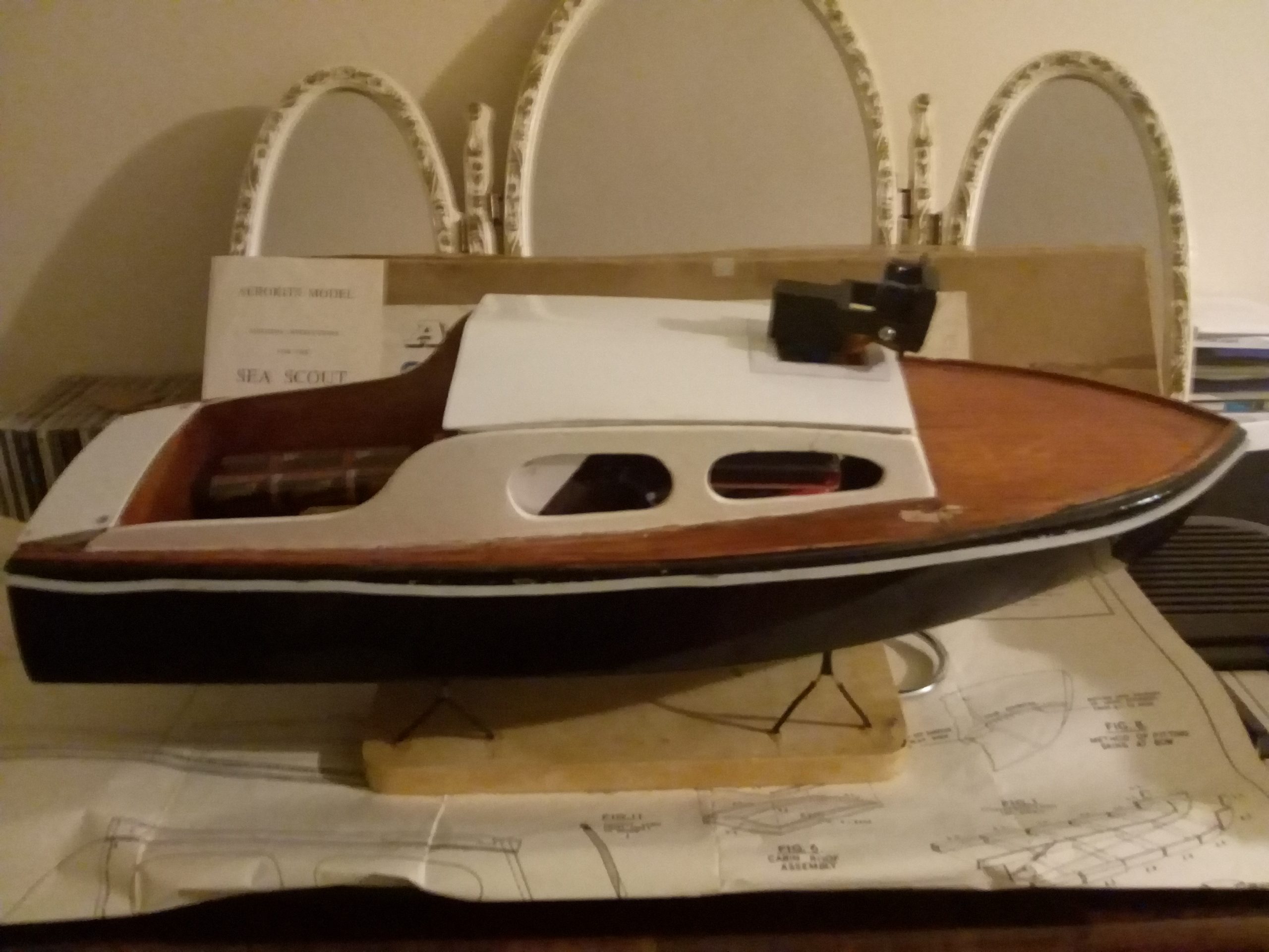
This wooden model cabin cruiser was hand kit-built, painted and assembled by the webmaster. It is now featured at the extremely useful Model Boat Website.
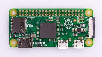
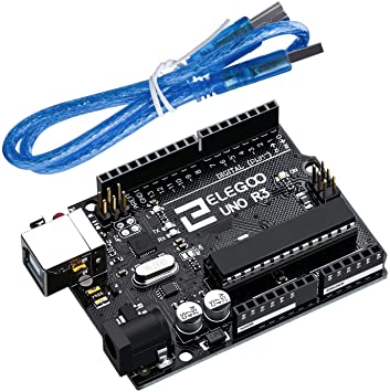
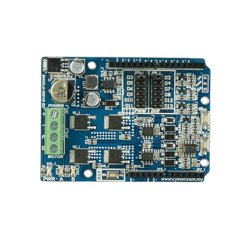
This microcontroller project was created to allow the remote operation of an optional Pi Camera (Pan and Tilt) controlled by a “Raspberry Pi Zero” and an “Arduino Uno” to navigate the boat . An “Arduino” phone app “Ardudroid” being used to control (Speed and Direction) other functions may be added (i.e. lights etc).
The Raspberry Pi also supports the “Arduino IDE” to create, compile, upload and maintain sketches e.g. Motor Driver and Helm servo.
The use of port forwarding on a home router was abandoned in favor of software from dataplicity.com where the Pi Zero was easily configured and works well.
HARDWARE
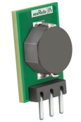
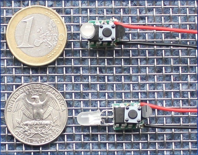
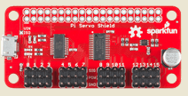
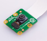
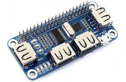
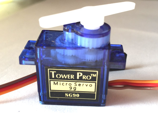
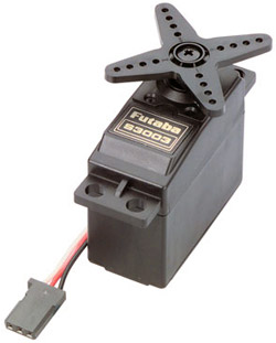
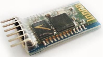
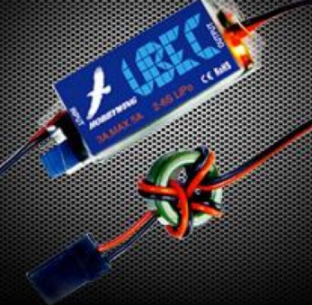
A table of components with links is provided below:
SOFTWARE
The “Rasperry Pi Zero W ” runs the most excellent “RPi Cam Web Interface by Silvan Melchior available here:
The Arduino mobile phone app “Ardudroid” controls the “Helm” servo and speed of the brushed motor it is written by Hazim Bitar and is available here.
Both of the above could be expanded e.g. control of navigation lights, siren and additional servo units.
Notes:
To setup the Pi Zero on “Buster” the steps on https://learn.sparkfun.com/tutorials/setting-up-the-pi-zero-wireless-pan-tilt-camera/all were followed. On completion it was found that the servos juddered considerably using the default pantilt.py so the pantily_50Hz_tuned.py was used to correct this. See the README file in home/pi/RPi_PanTilt_Camera_Kit/Firmware/ directory for the precautions taken with the supplied files.
Currently the power to the assembled unit is provided by 2 separate chargers as those available were not of sufficient (2 – 3 A) . The link was therefore cut on the servo board.
This project is under development and will include more functionality as time progresses.
